This style is officially called aviation snips. Actual tin snips are a little different but I like this style better. It has corrugated blades and leverage linkage to the blades that tin snips don’t have.
I have arthritis and cutting thicker things with scissors such as cardboard or heavy cloth, or yes, even tin, is difficult for me. I researched electric scissors but didn’t find anything that looked right. And the heavy-duty ones cost around $100.00 and I wasn’t about to spend that kind of money on scissors.
So I figured I’d try tin snips. Eureka! I love them for all of the above! They even just cut some hard plastic tubing that I didn’t think would work, but the tin snips went through it very easily. It’s easy now for me to cut all those thick things that used to cause me so much trouble. If you are having trouble cutting things, arthritis or not, get yourself some tin snips!
You can probably get them for under $10.00 and they’re fantastic! There are ‘straight cut’ style, and left cut and right cut style snips. Straight cut are best for straight-line cuts and all around use. Left cut make it easier to cut arcs to the left, right cut, easier to cut to the right. I didn’t want to be limited by a directional bias so I bought the straight cut and they’re working great!
I say “no thank you!” to ads like this one for wimpy scissors at really high prices now that I’ve discovered my tin snips!
For a long time I considered ‘o-ring’ to be the proper terminology for a drive belt in little DIY (do it yourself) animatronic projects. But when trying to purchase some o-ring drive belts, I discovered that the term ‘o-ring’ by itself is technically wrong. O-rings are for sealing things (like valves).
Better terminology when using them to drive things (transfer power from one location to another) is ‘o-ring drive belt’, or even ‘urethane belt’, which most o-ring drive belts are made from. (Rubber bands are made from, well, rubber). (So if you’re searching Google or YouTube for information on o-ring drive belts, you’ll have much better results using the full term instead of just searching for o-rings).
Rubber bands are for holding things together.
Rubber bands do not make great o-ring drive belt replacements, but they can work OK in simple applications.
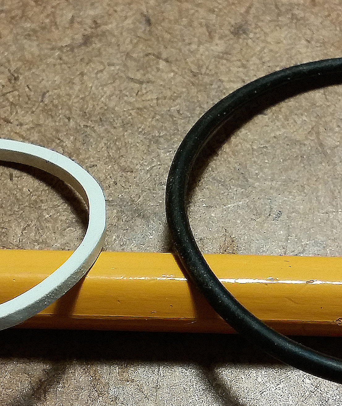
How to quickly tell the difference between o-rings and rubber bands: O-ring cross-sections are typically round and they stretch some, but not as much or as easily as rubber bands. Rubber bands typically have rectangular cross sections and stretch easily.
Imagine that you have a little hobby toy your are playing with and you are trying to rotate a shaft that is located a few inches away from your drive motor.
If you use a rubber band as the drive belt, the rubber band can ‘store’ energy as it stretches, and then it will finally transfer the power (rotate the shaft) after it has stretched to a certain point. This can make for a very uneven rotation, or it might just slip on the drive or driven shaft before ‘giving up’ its energy and result in complete failure to rotate the shaft at all.
The o-ring drive belt doesn’t stretch like the rubber band so rotation is much smoother. It also maintains its integrity much, much longer than rubber bands, which loose their strength and elasticity fairly soon.
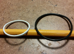
White rubber band, black o-ring shown below.
Here’s a little video I made to show the difference in drive smoothness:
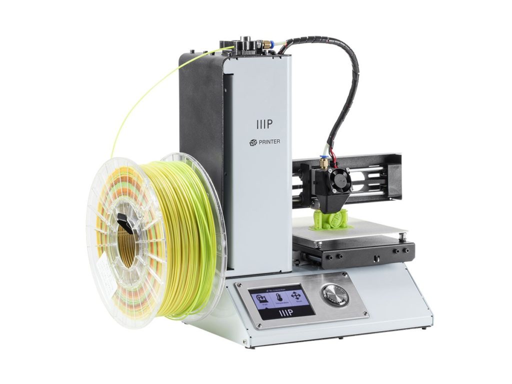
There are lots of great reviews of this one on you to youtube. I’ve been dying to get into 3D printing for quite some time and I decided to take the plunge with this one. The most appealing thing to me was the price 🙂
Is it possible to get a reasonably good printer for $200?!
Well, I was foaming at the mouth in excitement to get this — two months later I’ve barely touched it. I’ve actually found a couple of better solutions than the parts I was going to print, and I’ve been keeping busy with other things. I hope I’ll use it more soon…
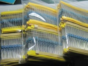
If you’re going to purchase resistors, don’t get these blue ones if you can avoid it. The color bands that indicate the resistance values don’t show up well enough against the blue background, so it’s next to impossible to read the resistance value on many of them. You often have to resort to an ohmmeter.
They’re OK if you only take them out of their marked container and use them once right away. I’m guessing they’re intended mostly for automated insertion machines on circuit boards that have small insertion holes to save space. But if you use them in a test circuit in your hobbies and then throw them in a box to use again with other loose resisters like I do, you can forget about being able to pick out the value you want again without breaking out your ohmmeter.
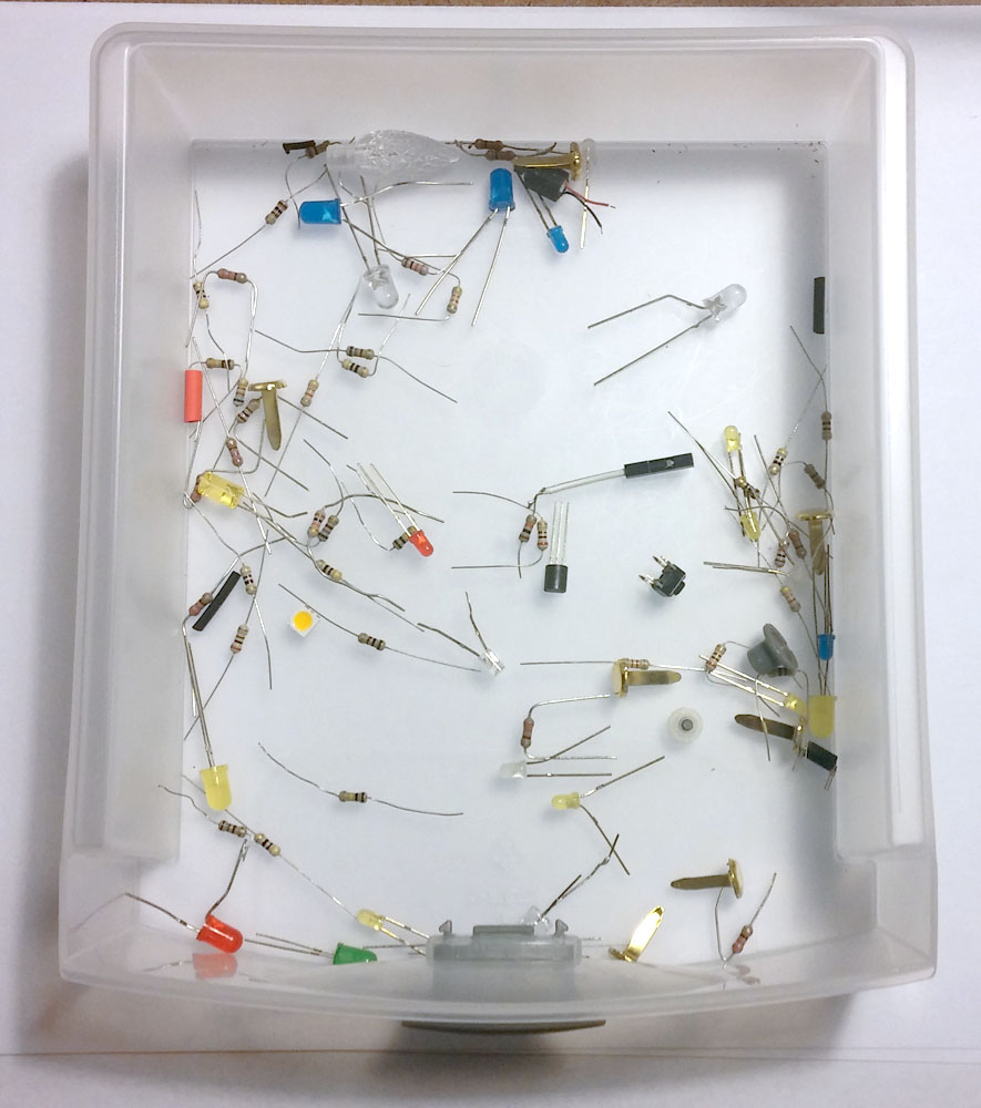
Here is a box that I use to toss miscellaneous parts into for easy access for re-use.
Looking for a certain resistor value on these beige ones is pretty easy, but trying to read a blue resistor value in a situation like this is next to impossible in my opinion. That’s why you don’t see any blue ones here — I threw them all in the trash.
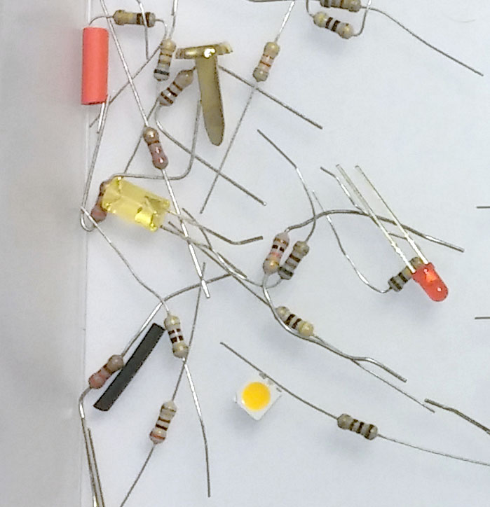
And watch out for the ones that have extremely thin leads. All of the blue ones and some of the beigeones that I’ve purchased from China via eBay have had very thin leads that are difficult to handle and they bend way too easily which means they kind of crumple when you try to insert them into test solderless breadboards.
If you’re not sure if you have the ‘angel hair’ leads, get out your caliper and measure them as shown in the video (I measured Angel hair = .013″ lead thickness — Better ones = .020″ lead thickness). It doesn’t look like a big difference, but it is!
Or if you just want to read their value in a circuit you’ve already built, forget it. I got a refund because they were so hard for me to read.
I understand that blue means they are metal film resistors with a 1% tolerance, and the beige ones are carbon with a 5% accuracy tolerance. If you need 1% tolerance you will be stuck with the awful blue ones.
The blue ones are hard enough to read, and cheap enough, where if I had to use them, I’d just throw them away after using them in a test circuit, rather than keeping them in my junk box to use again like I do the beige ones. Trying to stay organized and returning them to their marked container (usually just a plastic bag) is way too much messing around.
I’m happy with 5% tolerance of the beige ones and I stick with them. For most hobby projects using Arduinos, LEDs, relays, etc., 5% tolerance is fine. But just like the blue ones, you have to be careful not to get the beige resistors with the wimpy leads.
I suggest getting the resistors with a beige background and the thicker leads (if the tolerance is acceptable in your projects).
Wimpy Resistor Leads
I found beige resistors with fat leads at www.newark.com and www.microcenter.com . I actually got Newark to send me a couple of samples before I bought. Places like Newark who supply to commercial companies will send out samples, but that’s a service intended for companies who buy large quantities. You can try to get a couple of free samples but you’ll probably just have to buy some from most places and hope for the best.
I think I’d just buy from Amazon from now on. It’s so easy to return stuff, I’d pick a vendor with an assortment that looks good and then just return them if they’re the wimpy leads and try a different vendor on Amazon. It’s time we stood up against wimpy resistor leads and said enough is enough! 🙂
If you must purchase the blue metal film 1% resistor kits, this set looks pretty good. But beware, somebody reviewed them and mentioned the same problems I’ve had — thin leads and extremely difficult to read the color codes.
I thought I would offer some ideas on different ways to open box lids. My main motivation has been finding a good way for lifting the lid of small Halloween coffin props, but the techniques can be used for many other applications as well.
I love to play around making these things as a hobby, but I need to make smaller versions of these because I don’t have enough room for full-sized ones. Here’s an example of a nice full-sized one by MrTmartindale on YouTube.
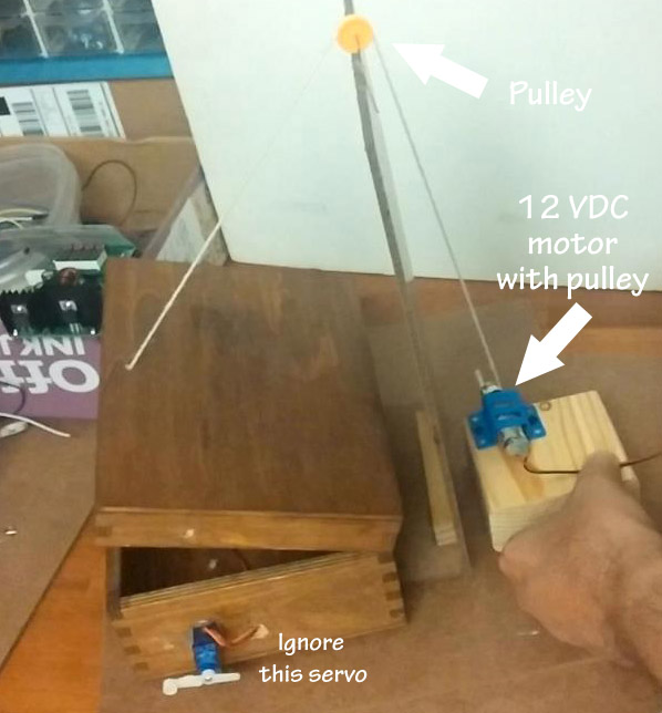
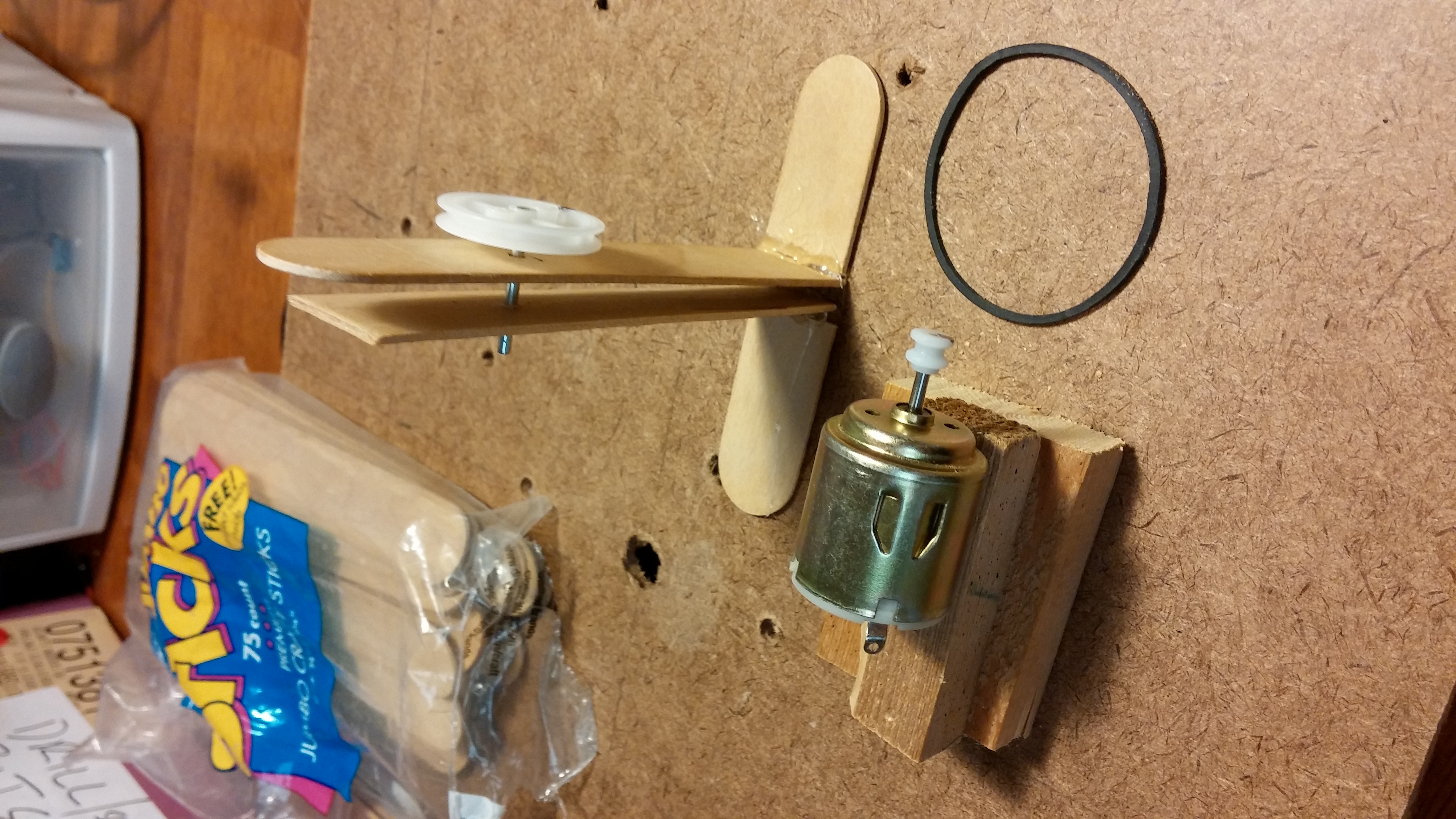
Seeing as I was recently playing around with pulleys I thought I would start with probably the most basic way to lift a lid — with a string!
There are a lot of potential problems with this arrangement:
It’s visible.
You need to reverse the polarity on the motor for up and down directions.
It takes up a lot of space.
It needs a lot of parts: string, string pulley, pulley support, motor, motor pulley, motor mount, and some way to reverse the motor direction.
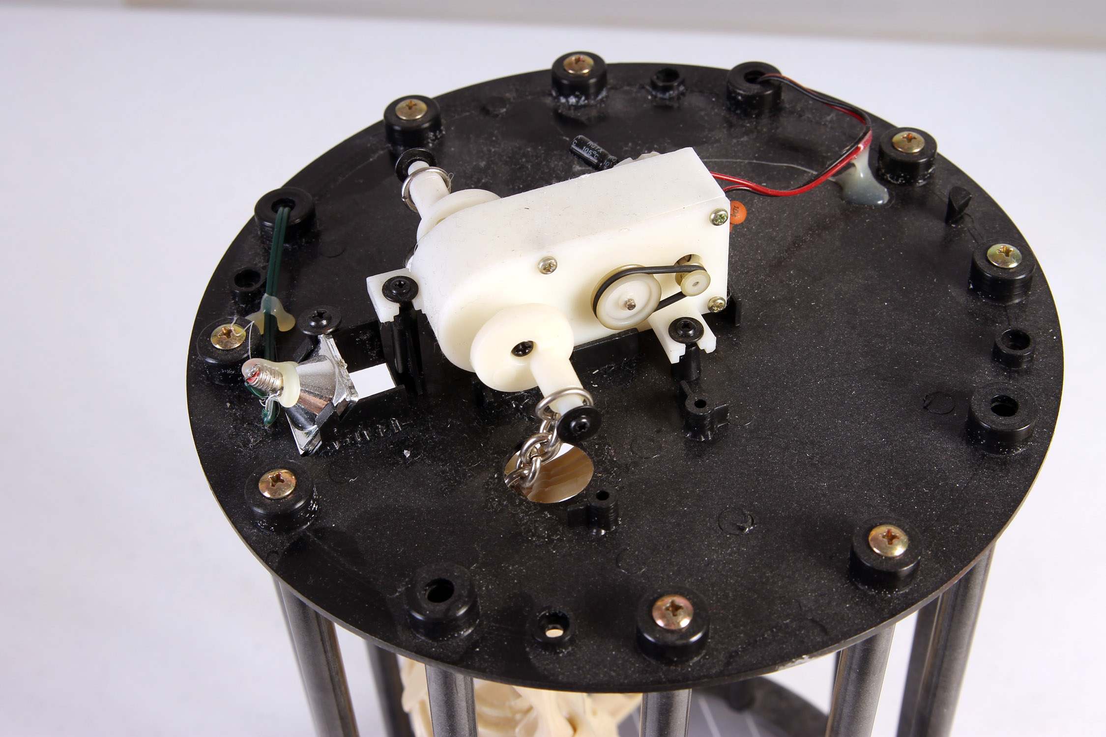
Today I’m starting to experiment using pulleys. They’re not used all that much in animatronics. I’m guessing it’s because they’re not as strong, predictable, or reliable as gears. But sometimes they can be useful. I see them a lot on the outside of gearboxes like this one, where the inside is chock full of gears (click photos to open larger versions in a new window):
I’m guessing this is the case when they don’t have room inside a standard gearbox (if there is such a thing in animatronic toys) and when speed, direction, or power transfer are not critical. Although, I wonder why they just don’t re-design the gearbox to accommodate this arrangement with gears? I have come across two toys where the drive belt has broken and rendered the toy’s animations useless.
Now these little gearboxes are tremendous to use in small animatronics, but it’s not possible for most of us to design our own gearboxes on this small of a scale. So pulleys are one way to drive our own hobby animatronics.
Enter my beginning learning design!
The first thing I had to do was get myself a little hobby motor. They are easy to find in just about any animated toy. They are pretty generic can usually run on anything from 1-1/2 to 6 volts DC or so. The problem with using just the motor is that they spin way too fast (around 10,000 RPM), and they have no power. Gears, or pulleys, are used to slow down the rotation and increase power.
In my previous post I talked about using a motor, a cam, and a switch to fire a solenoid. That just wasn’t going to work because it was too hard to get the right pace of the solenoid firing. The motor voltage changed its speed, and it was too difficult to adjust the cam shape and to fire the solenoid properly.
In this post I’m showing how I used the Arduino Nano to control the firing rate of the solenoid instead of a rotating cam. With the Arduino, it’s a 30-second program change to adjust the rate of the solenoid firing as opposed to the ridiculously difficult process with motor and cams.
The video below shows the solenoid firing once per second by using the default settings in the sample ‘Blink’ program that is included with the Arduino. Then I made a simple program change in the Arduino to speed up the solenoid. This is soooo much easier than cams and motors!
Trying to find a way to mount things like motors, solenoids and switches is often a big challenge. Trying to find the right bracket, the right screws, and the right locations for those items in your experimental projects can be tough.
So I thought I’d show a few tips and tricks that I use.
First, my goal: I was trying to set up a little solenoid to bang against a miniature box to make a ‘chattering’ effect for a mini ‘monster in a box’ project, kind of like this Halloween monster in a box video (fast forward to about 1 min, 25 seconds to see the box chatter).
I started by experimenting with a little hobby motor. It wasn’t powerful enough to attach a cam straight away to rattle the box on its own so I had to find gears or levers, or something, to get some mechanical advantage.
The box in the video uses a cam attached to an electric drill, but I wanted something much smaller for my little project.
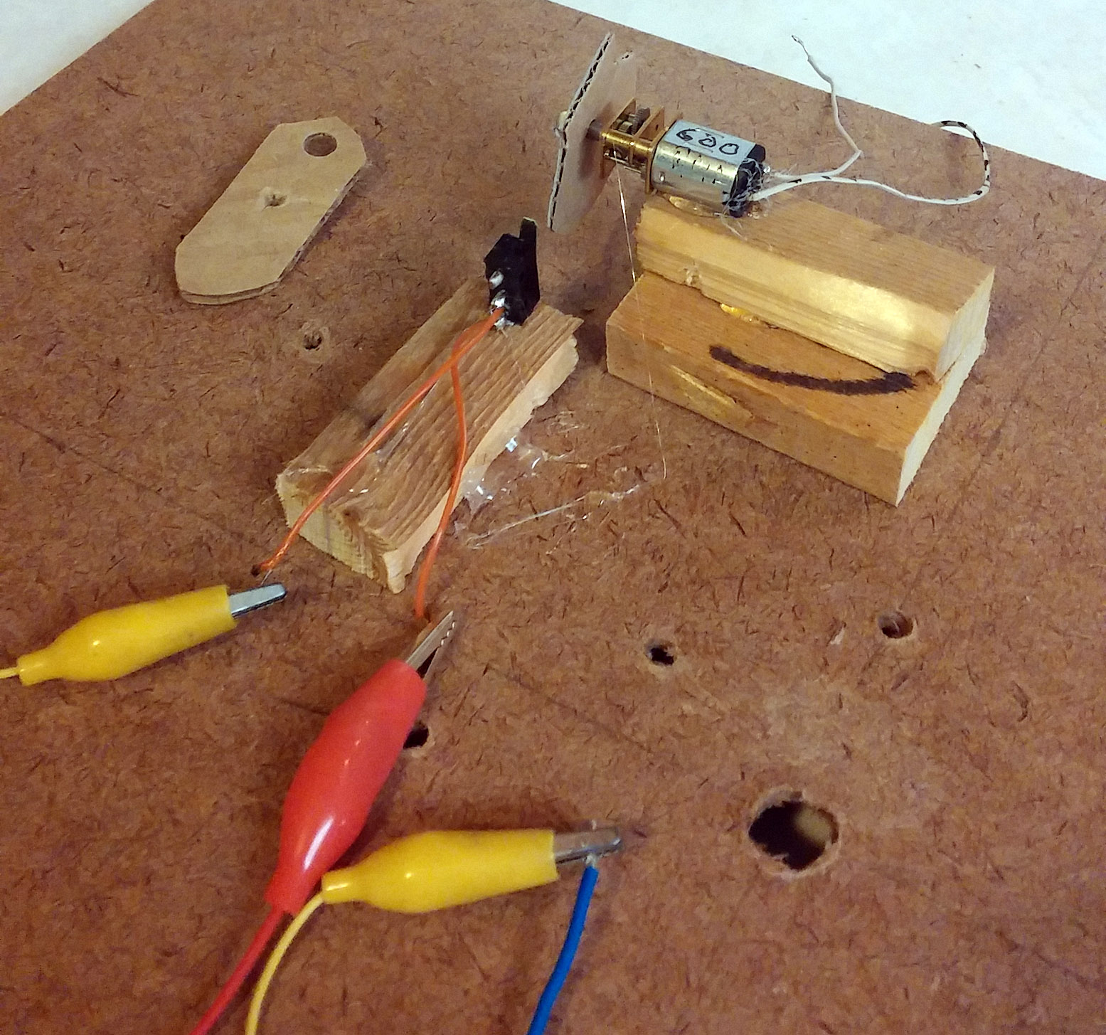
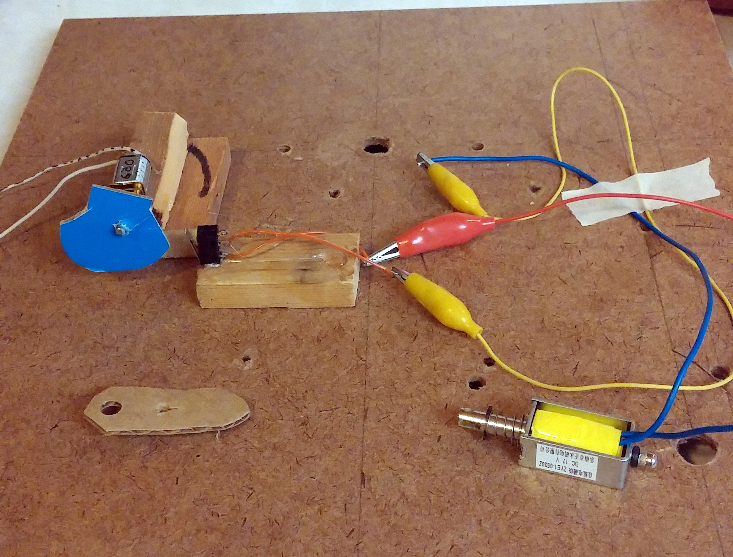
I started out using a cam to trigger a micro switch, which would energize a solenoid in rapid succession. (See my next post to see the solenoid fire.)
Instead of trying to find the right size and shape of a motor mount for my initial testing of things, I just used hot glue to secure some little blocks of wood to my test base (a 12″ square piece of press board). Then I put a little dab of hot glue on the motor and on the micro switch to secure them to the proper height of wood blocks.
Click on the photos to see larger versions.
Using blocks of wood is a fantastically simple way to make the right heights and locations. I was able to put away my box of sheet metal, tin snips, and other miscellaneous hard-to-use metal mounting hardware!
You can see my little blue cam that I also used hot glue for. I glued it to the motor shaft for a temporary attachment. Hitting the switch with the first cam — the brown pointy one you can see laying there — didn’t keep the switch activated long enough to fire the solenoid properly so I made the blue cam that kept the switch activated for about 5 times as long.The hot glue made it very easy to swap cams and re-glue.
The motor rotates at 300 to 600 RPM depending on the voltage applied (3 to 6 volts). That was way too fast with either cam, so I had to find another solution (see my post about using the Arduino instead of a motor). But the mounting techniques of wood blocks and hot glue have been a big headache-reliever for me over trying to find or fabricate metal mounts.
Of course you can purchase motors online, but you can get them for a much reduced price (usually) if you’re lucky enough to have thrift stores in your area like the Goodwill. As an extra bonus, you can often scavenge things from your thrift store purchases that are worth more than what you paid for the item.
For instance, I often scavenge switches, power adapters, batteries, connectors, speakers, magnets, LEDs, etc. from toys and tools I get at the thrift stores.
But let’s get back to drills for sources of motors. Doing that can work great, but I found a few pitfalls that you might want to watch out for.
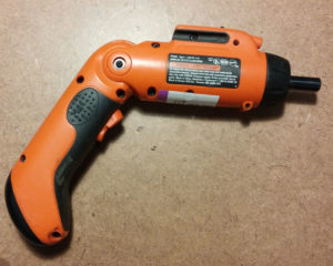
Here is a cordless drill like one that I scored from the Goodwill for $4.99. I though it was a great price for a strong, low voltage, dc motor. I was wrong.
It had a charger with it that I thought would be worth the price of the drill alone. But to my surprise, its output was 3.6 VAC — that’s AC folks. And you don’t usually want an ac power brick for most of your projects. So that wasn’t the great advantage I thought it was going to be. But I did get the motor out of it. More on that in a minute.
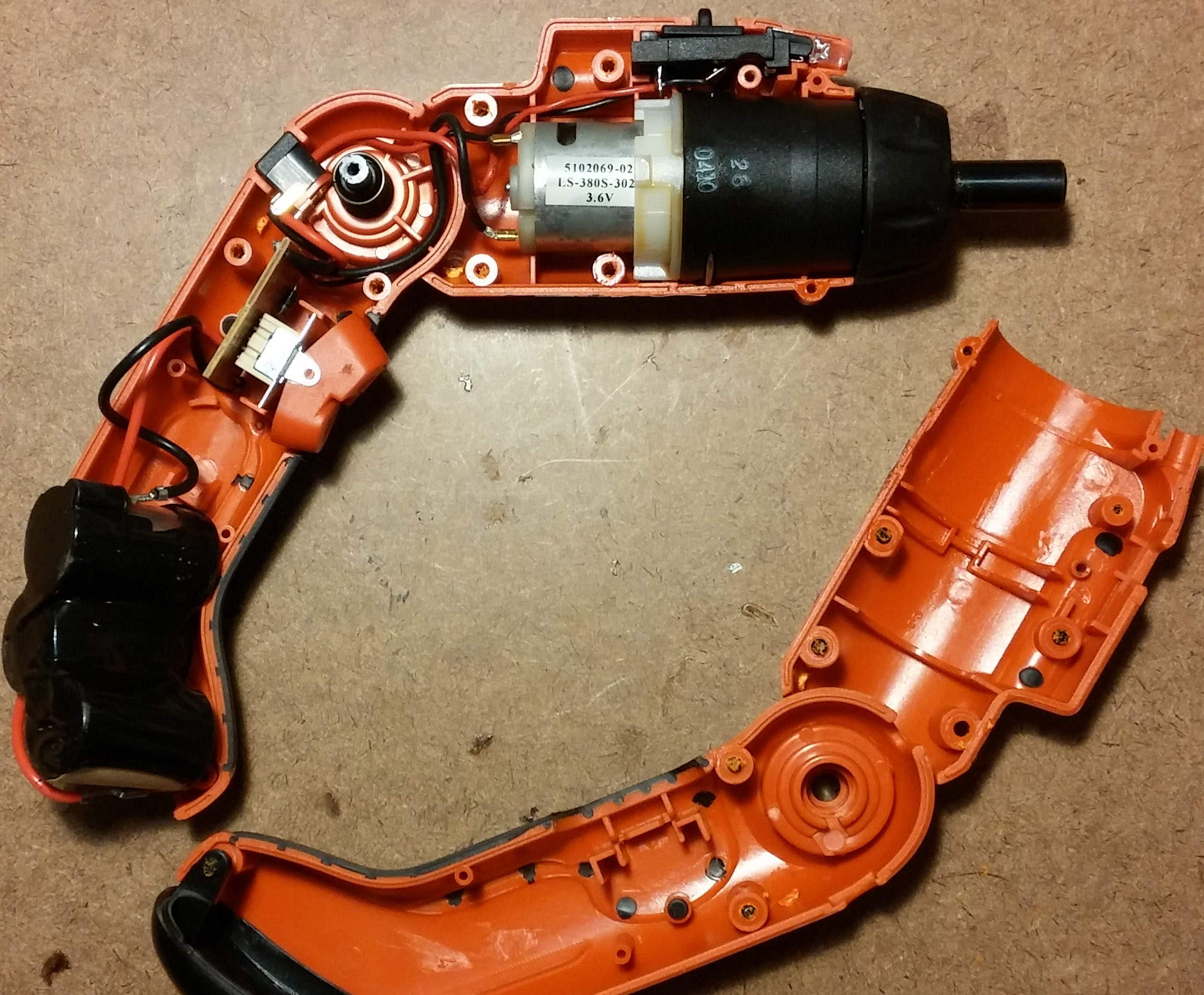
And then I found another cordless drill that did not have a charger with it, but it stated on its label that it required a DC charger. So I bought it partially for the motor and partially to take it apart to see if it different guts than the AC-charged other one.
But neither one is that great because I think the motors require too much current. At least my little 500 milli amp power supply won’t run them.
You might need a torx screwdriver to get these apart. I had some bits which worked great for most screws.
But one screw was too deep so luckily I had a torx screwdriver. The most common size is a #10.
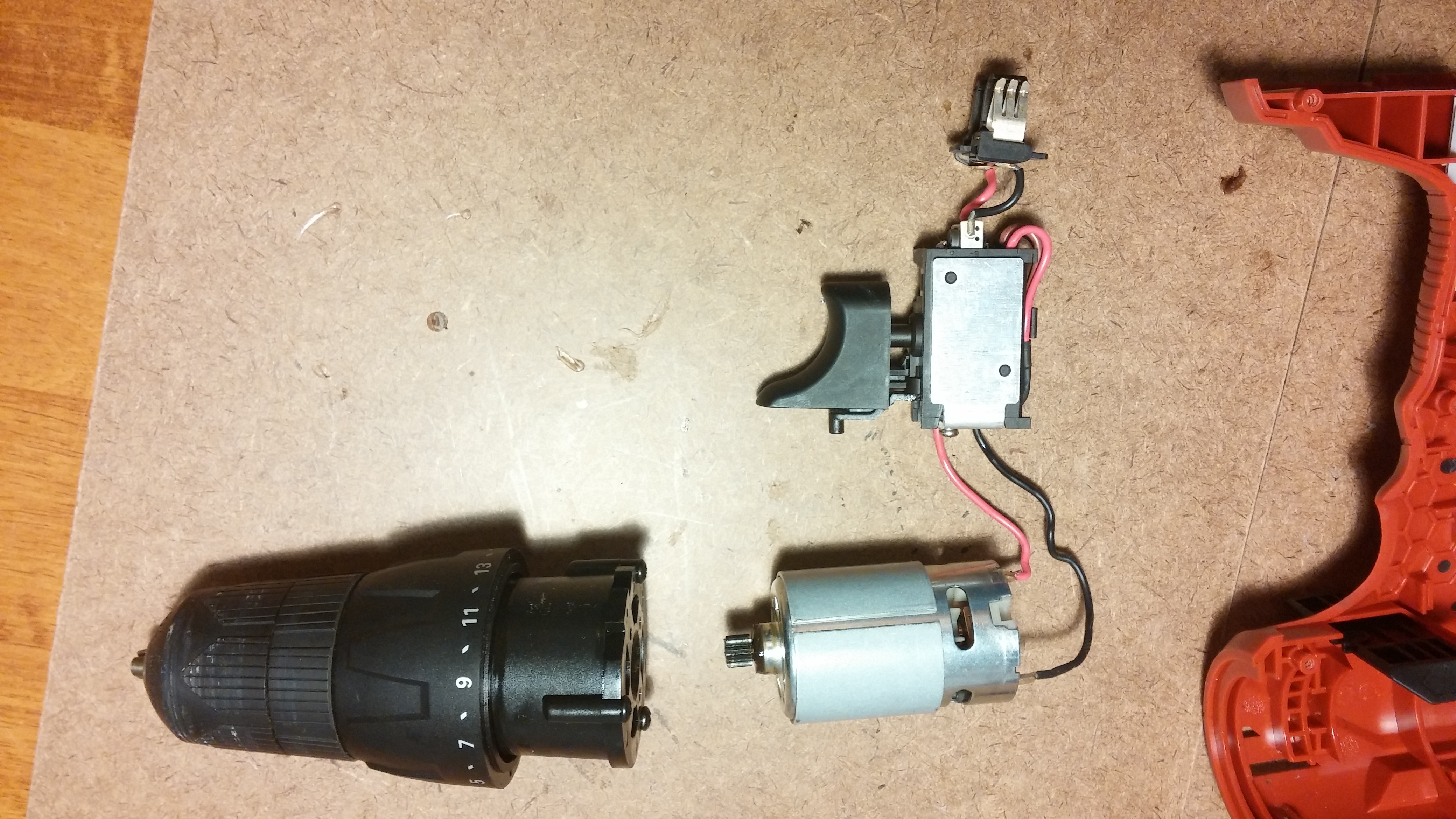
I think it’s better to go for the 12 volt cordless drills — they require 1 to 3 amps but you can get power supplies that will supply that current easier than you can find 3 volt supplies for the smaller cordless drills that will supply amps of current.
A series circuit is one in which items are arranged in a chain, one following the other, so the current has only one path to take. The current is the same through each item.
Series circuits are used for several reasons:
1. To increase a voltage source.
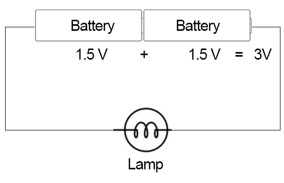
The following is true of any standard battery, but let’s use the AA battery as an example. If you put one AA battery in a circuit, you will have a power source of 1.5 volts because that’s the voltage of a standard AA battery.
If you want 3 volts, you can place two AA batteries in series which gives you 1.5 V + 1.5V, which equals 3V.
Put three AA batteries in series and you will get 4.5 volts, etc.
More coming soon.
Also see: http://physics.bu.edu/py106/notes/Circuits.html