Repairing a bad JQ6500 sound/voice/music/MP3 module

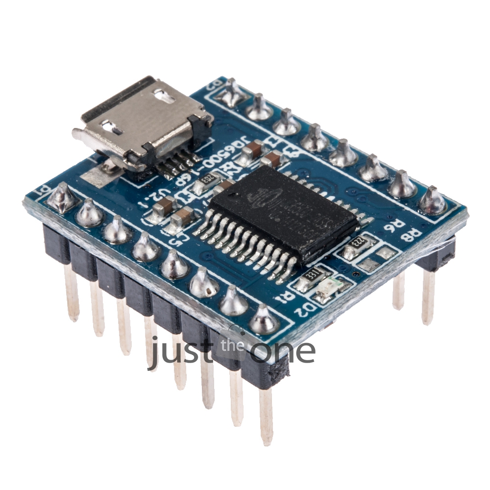
I have been using the JQ6500 modules for a couple of years in conjunction with Arduinos to add simple sounds to my little Halloween projects. In the past they have all worked just fine.

Back in August of 2017 I ordered 5 more of them from http://stores.ebay.com/chivazhu/   One just didn’t do anything when I plugged it in and four failed with the message that Windows could not recognize the thing. Obviously I don’t recommend that vendor!

(Yes, I ran out of my current supply and finally opened the package of bad ones about six months after I received them — let that be a lesson — test your stuff when it arrives — not six months later when you need them, and can’t even get a refund.)

I ordered from this vendor in May of 2018 and received them with no sound program either. So I do not recommend this vendor for them: https://www.ebay.com/usr/onlinehappyshopping?_trksid=p2047675.l2559

To help you maybe find ones that work when ordering from eBay/China, the ones I bought from other vendors have worked fine. Two of the vendors no longer sell them, but http://stores.ebay.com/caelectronics8/  still does, and the ones I got from them did work. In May of 2018 I got good ones from this vendor too: https://www.ebay.com/str/txhangelectronic

Just because I got good ones from them in the past is not a guarantee that I will in the future. And because I’ve had problems with other products from China, and because they take so long to get here, I often order from two different vendors when I buy things from China now. (At least I do that for the inexpensive things.) And I order a different quantity from each vendor so I know which ones came from which vendor (the packages they arrive in are labeled in Chinese so you can’t tell who they’re from unless you can read Chinese).

If you order two from each vendor, and one set is bad, you won’t know which vendor the bad ones came from. But if you order two from vendor A, and three from vendor B, then you can tell who is who.

Back the to problem… I looked the bad ones over closely and noticed that a few of the pins on the main chip were not soldered to pads. The pads didn’t even look like they had metal on them to be soldered to. But I tried to solder them anyway. Of course, with surface mount chips, repair is never easy and I ruined it. Two down, three to go. (It turns out those pins look that way on all of them and are not the problem.)

So I went looking on the internet for solutions. I googled ‘jq6500 doesn’t work’. I wasn’t hopeful, but I did find a fair amount of information about the problem. I learned from this site https://sparks.gogo.co.nz/jq6500/index.html  that apparently some of the manufacturers don’t include the Chinese music program on the chip that’s necessary for the thing to work!

That site has some good info, including links to other info and solutions. One link went to a guy who has a fix! He never comes out and says it (that I can find) but I think he created the fix. That site is https://github.com/NikolaiRadke/JQ6500-rescue-tool

I don’t really understand github so I did some more research. I found this video which really got me started in the right direction https://www.youtube.com/watch?v=9h_RWsfRnY4&vl=en

He offers instruction on using VMware Player to fix the  problem for Linux, but it helped me a lot even though I’m using Windows 10. I decided to make a boot CD seeing as I still have about 100 blank CDs laying around, rather than try the VMware.

Check his follow up video that helped me on the second problem you’ll probably run into about compatibility if you use Windows 8 through 10 https://www.youtube.com/watch?v=dcY47Dzef

He refers to the github site too, so I figured it was ok to download a .exe file from there.

So I followed some of the instructions from the github download, but they weren’t crystal clear to me on how to create a boot disk, so I did more research.

I found several mentions of ImgBurn for creating a boot disk; one mention was from the Microsoft site help pages. So again, as much as I hate to do it, I downloaded another .exe file from the ImgBurn site http://www.imgburn.com/

They don’t have great instructions either, but I managed to get through it and created a bootable CD with the Chinese Music program on it using ImgBurn!

I was able to follow the rest of the instructions from the github download page and now two of the JQ6500 modules work properly when plugged into a USB port. One works properly on a separate 5V power supply with no USB cable connected. The other one does not work with the USB unplugged and using a separate 5V supply.

The moral of this story? Test these (and all of your electronics) when you receive them, not six months later. And for these things, hope you get some that work and just get a refund for the ones that don’t. In my opinion, if you don’t need them right away, it’s just not worth the trouble to try to repair them.


5050 SMD (Surface Mount Device) LED Demo

Learn a little about a 5050 SMD (Surface Mount Device) LED. See my test bed and how I test warm white and cool white 5050’s.

They’re called 5050 because their dimensions are 5.0 x 5.0 mm. They operate at 60mA, 3V to 3.2 Volts. In my video I show that there are actually 3 LEDs in each 5050 package. So you could just light one or two of those and only use 20 or 40 mA if you want to reduce the current used.

I get the 5050 LEDs from Amazon here

Here’s a link to the copper tape

Digital Calipers

I get my alligator clip test leads locally, but these look pretty good if you need to order online

I have several of the battery holders with a built-in current-limiting resistor and on/off switch. Let me know if you’d like to purchase one for $3.95 and free shipping.

Basic Arduino LED Circuit

A short video showing how to extend a simple circuit out from the Arduino.

Here’s a source for breadboards on Amazon: http://Amazon: http://amzn.to/2CHpeLK

You can get a set of 3 Arduino Nanos here: http://amzn.to/2mbrbsG .  You can’t beat the price of these Chinese clones, but know that you will need to solder the headers on,  and you may need to download a driver for these Chinese clone boards. See how I do that in my video here: http://mechatronicsworkshop.com/index.php/2017/12/14/arduino-nano-prep/

You can purchase clones with the headers already soldered on if you search for them. Be careful buying clones — these appear to come from a warehouse in the U.S. so shipping is quite fast to the U.S.  But be careful that you don’t buy them from  a supplier who ships from China unless you or ok waiting for three to four weeks to get them delivered.

If you want to pay more and have the headers soldered on and no need to download a driver, go to the Arduino.cc site and purchase the original boards there.

Elenco is a great company to find larger breadboards, and all sorts of fun electronic stuff: http://amzn.to/2maSIun


The L298N H-bridge motor controller module basics

Get an L298N module at Amazon

Oh boy, was I confused about this module at first! I found a fair amount of bits and pieces about it, but could not find the complete info that I was looking for. So I decided to create this tutorial for others who want to understand it better. I’m not an expert, but I have figured it out well enough to make what I think is a very clear and complete basic ‘primer’ on this device. Whether it’s right for your project is up to you to determine, but here’s info about the module itself, and especially about the mysterious jumpers (at least they were the biggest mystery to me).

You can see the data sheet on the ST website here: http://www.st.com/en/motor-drivers/l298.html .

You could just purchase the chip and component parts and wire up your own parts, but this complete module is probably cheaper than the combined parts, and it’s certainly more convenient. As of January, 2017, the modules are selling on ebay for under $2.00! At this price they’re from China of course, but you can purchase them at higher prices in the United States if you can’t wait for the long shipping times from China.

I’ve read in forums that the L298 chip is about 15 or 20 years old, so there are better(?) chips available now. People seem to like the Pololu A4988 https://www.pololu.com/product/1182 .  Stepper motor current limiting is apparently one of the big improvements, but none of the current-limiting chips come in this neat module format that I’m aware of. So this L298N module is fun and handy, certainly great for testing and little projects, but be careful if you need current-limiting features when driving stepper motors.

You can see the Input (IN) pins clearly, and here is a photo of the enable pins with me removing the jumper block. Click the photo to see a larger version.

L298N Truth Table

Get an L298N module at Amazon


Get fun motors with robot wheels.
A tremendous buy!


Get an L298N module at Amazon

Arduino project with blinking button, siren and LEDs

A fun little project idea that tempts potential ‘victims’ with a blinking button that says, “Do NOT Press This Button!” When pressed, it sets off a siren and blinking LEDs. Let’s see who can resist!

I think it’s better to hide the cable that connects the button to the LED box. I just used what I had handy to cover the cable — two Christmas toys I had nearby. I would use something more appropriate if this was going to be anything more than a quick test setup. Wireless would be the best… maybe next time.

If you’re an Arduino fan, here’s a little side note about the LEDs. It was necessary to blink the LEDs using millis instead of delay so the button LED, the siren, and the different blink rates of the LEDs all worked at the same time.

Buying resistors

If you’re going to purchase resistors, don’t get these blue ones if you can avoid it. The color bands that indicate the resistance values don’t show up well enough against the blue background, so it’s next to impossible to read the resistance value on many of them. You often have to resort to an ohmmeter. 

They’re OK if you only take them out of their marked container and use them once right away. I’m guessing they’re intended mostly for automated insertion machines on circuit boards that have small insertion holes to save space. But if you use them in a test circuit in your hobbies and then throw them in a box to use again with other loose resisters like I do,  you can forget about being able to pick out the value you want again without breaking out your ohmmeter.

Here is a box that I use to toss miscellaneous parts into for easy access for re-use.

Looking for a certain resistor value on these beige ones is pretty easy, but trying to read a blue resistor value in a situation like this is next to impossible in my opinion. That’s why you don’t see any blue ones here — I threw them all in the trash.

And watch out for the ones that have extremely thin leads. All of the blue ones and some of the beige ones that I’ve purchased from China via eBay have had very thin leads that are difficult to handle and they bend way too easily which means they kind of crumple when you try to insert them into test solderless breadboards.

If you’re not sure if you have the ‘angel hair’ leads, get out your caliper and measure them as shown in the video (I measured Angel hair = .013″ lead thickness — Better ones = .020″ lead thickness). It doesn’t look like a big difference, but it is!

Or if you just want to read their value in a circuit you’ve already built, forget it. I got a refund because they were so hard for me to read.

I understand that blue means they are metal film resistors with a 1% tolerance, and the beige ones are carbon with a 5% accuracy tolerance. If you need 1% tolerance you will be stuck with the awful blue ones.

The blue ones are hard enough to read, and cheap enough, where if I had to use them, I’d just throw them away after using them in a test circuit, rather than keeping them in my junk box to use again like I do the beige ones. Trying to stay organized and returning them to their marked container (usually just a plastic bag) is way too much messing around.

I’m happy with 5% tolerance of the beige ones and I stick with them. For most hobby projects using Arduinos, LEDs, relays, etc., 5% tolerance is fine. But just like the blue ones, you have to be careful not to get the beige resistors with the wimpy leads.

I suggest getting the resistors with a beige background and the thicker leads (if the tolerance is acceptable in your projects).

Wimpy Resistor Leads

I found beige resistors with fat leads at www.newark.com and www.microcenter.com . I actually got Newark to send me a couple of samples before I bought. Places like Newark who supply to commercial companies will send out samples, but that’s a service intended for companies who buy large quantities. You can try to get a couple of free samples but you’ll probably just have to buy some from most places and hope for the best.

I think I’d just buy from Amazon from now on. It’s so easy to return stuff, I’d pick a vendor with an assortment that looks good and then just return them if they’re the wimpy leads and try a different vendor on Amazon. It’s time we stood up against wimpy resistor leads and said enough is enough! 🙂

If you must purchase the blue metal film 1% resistor kits, this set looks pretty good. But beware, somebody reviewed them and mentioned the same problems I’ve had — thin leads and extremely difficult to read the color codes.

Using Arduino Nano and a relay to fire a solenoid

In my previous post I talked about using a motor, a cam, and a switch to fire a solenoid. That just wasn’t going to work because it was too hard to get the right pace of the solenoid firing. The motor voltage changed its speed, and it was too difficult to adjust the cam shape and to fire the solenoid properly.

In this post I’m showing how I used the Arduino Nano to control the firing rate of the solenoid instead of a rotating cam. With the Arduino, it’s a 30-second program change to adjust the rate of the solenoid firing as opposed to the ridiculously difficult process with motor and cams.

The video below shows the solenoid firing once per second by using the default settings in the sample ‘Blink’ program that is included with the Arduino. Then I made a simple program change in the Arduino to speed up the solenoid. This is soooo much easier than cams and motors!

Series Circuit Defined

A series circuit is one in which items are arranged in a chain, one following the other, so the current has only one path to take. The current is the same through each item.

Series circuits are used for several reasons:

1. To increase a voltage source.

The following is true of any standard battery, but let’s use the AA battery as an example. If you put one AA battery in a circuit, you will have a power source of 1.5 volts because that’s the voltage of a standard AA battery.

AA-battery


If you want 3 volts, you can place two AA batteries in series which gives you 1.5 V + 1.5V, which equals 3V.

AA double batteries and lamp


Put three AA batteries in series and you will get 4.5 volts, etc.

More coming soon.


Also see: http://physics.bu.edu/py106/notes/Circuits.html

Your First Electronic Circuit!

So you want to learn about electronics! Good for you! The sky is the limit when it comes to this field, but let’s start with a very simple circuit.

Lighting up a light emitting diode (LED).

The entire circuit is very simple — it consists of an LED, a power source (batteries), and a resistor to limit the current through the LED.

Light emitting diodes will emit light when a voltage is applied to them and current flows through them. Different colors and types of LEDs may require different voltages and currents, but a standard red LED requires 1.7 volts and .02 amps (20 milliamps, or 20 mA).

Here is a how to build your circuit if you’re a very beginner without many tools yet.

basic LED circuit

I have two AA batteries (1.5 volts each) that are connected in series to make about 3 volts. (Click here to learn about series connections.)

They are in a little battery holder with alligator clips that I soldered on to make the connections easier.connected to the LED and a current-limiting resistor.

I used an extra alligator clip to connect the resistor to the LED. You could use a paper clip, or just wind them together.

Here is what the circuit looks like in a schematic diagram:

basic_circuit_schematic

Even this simple circuit needs a little forethought.