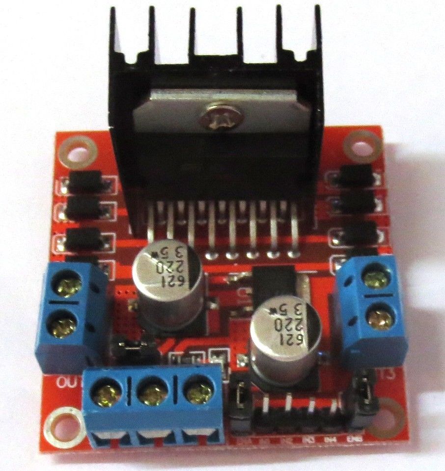
Get an L298N module at Amazon
Oh boy, was I confused about this module at first! I found a fair amount of bits and pieces about it, but could not find the complete info that I was looking for. So I decided to create this tutorial for others who want to understand it better. I’m not an expert, but I have figured it out well enough to make what I think is a very clear and complete basic ‘primer’ on this device. Whether it’s right for your project is up to you to determine, but here’s info about the module itself, and especially about the mysterious jumpers (at least they were the biggest mystery to me).
You can see the data sheet on the ST website here: http://www.st.com/en/motor-drivers/l298.html .
You could just purchase the chip and component parts and wire up your own parts, but this complete module is probably cheaper than the combined parts, and it’s certainly more convenient. As of January, 2017, the modules are selling on ebay for under $2.00! At this price they’re from China of course, but you can purchase them at higher prices in the United States if you can’t wait for the long shipping times from China.
I’ve read in forums that the L298 chip is about 15 or 20 years old, so there are better(?) chips available now. People seem to like the Pololu A4988 https://www.pololu.com/product/1182 . Stepper motor current limiting is apparently one of the big improvements, but none of the current-limiting chips come in this neat module format that I’m aware of. So this L298N module is fun and handy, certainly great for testing and little projects, but be careful if you need current-limiting features when driving stepper motors.
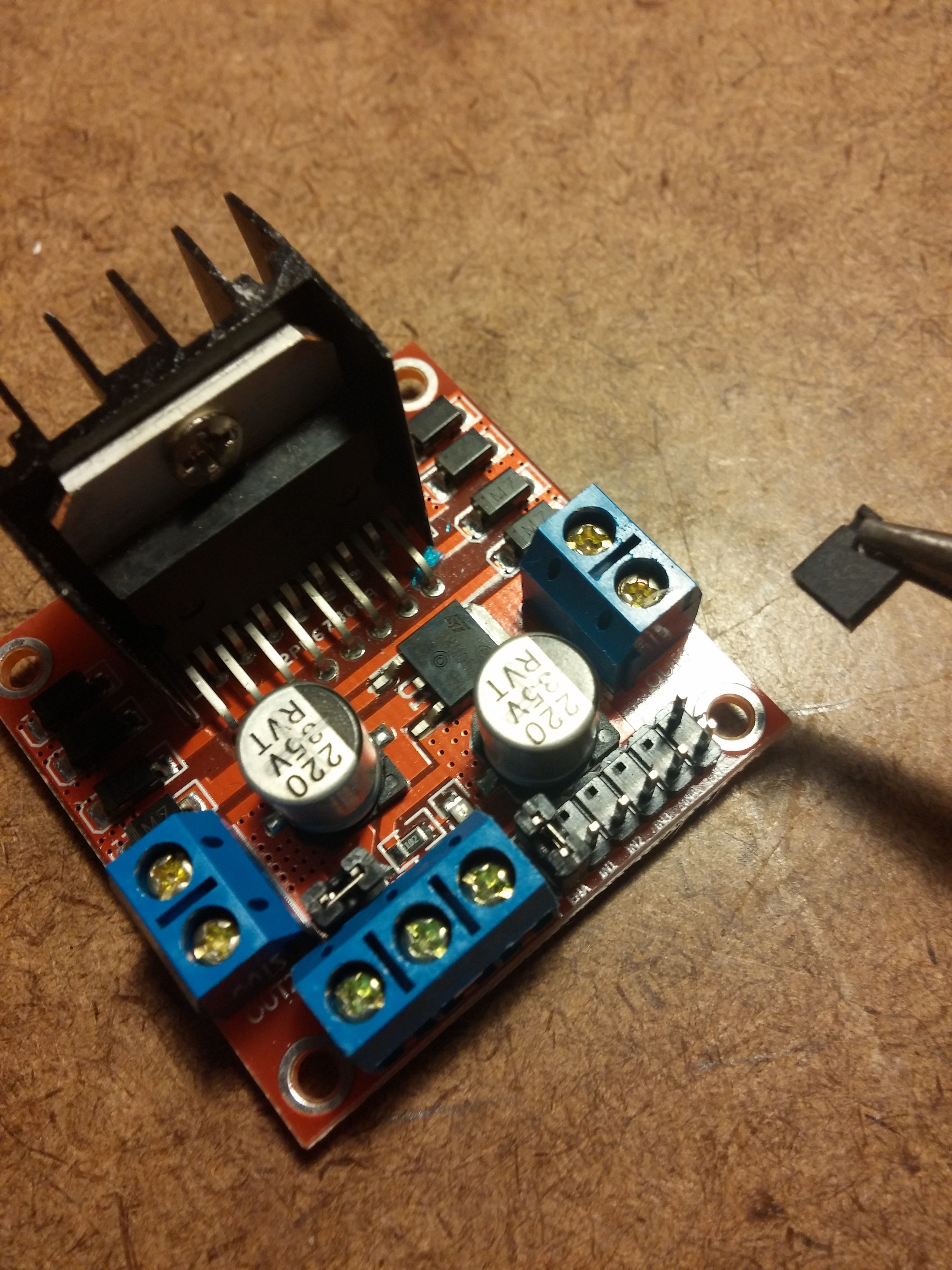
You can see the Input (IN) pins clearly, and here is a photo of the enable pins with me removing the jumper block. Click the photo to see a larger version.
Get an L298N module at Amazon
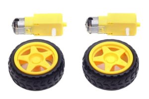
Get fun motors with robot wheels.
A tremendous buy!
Get an L298N module at Amazon